互联网出口和 VPN 混合场景
互联网出口和 VPN 混合场景
网络拓扑与需求
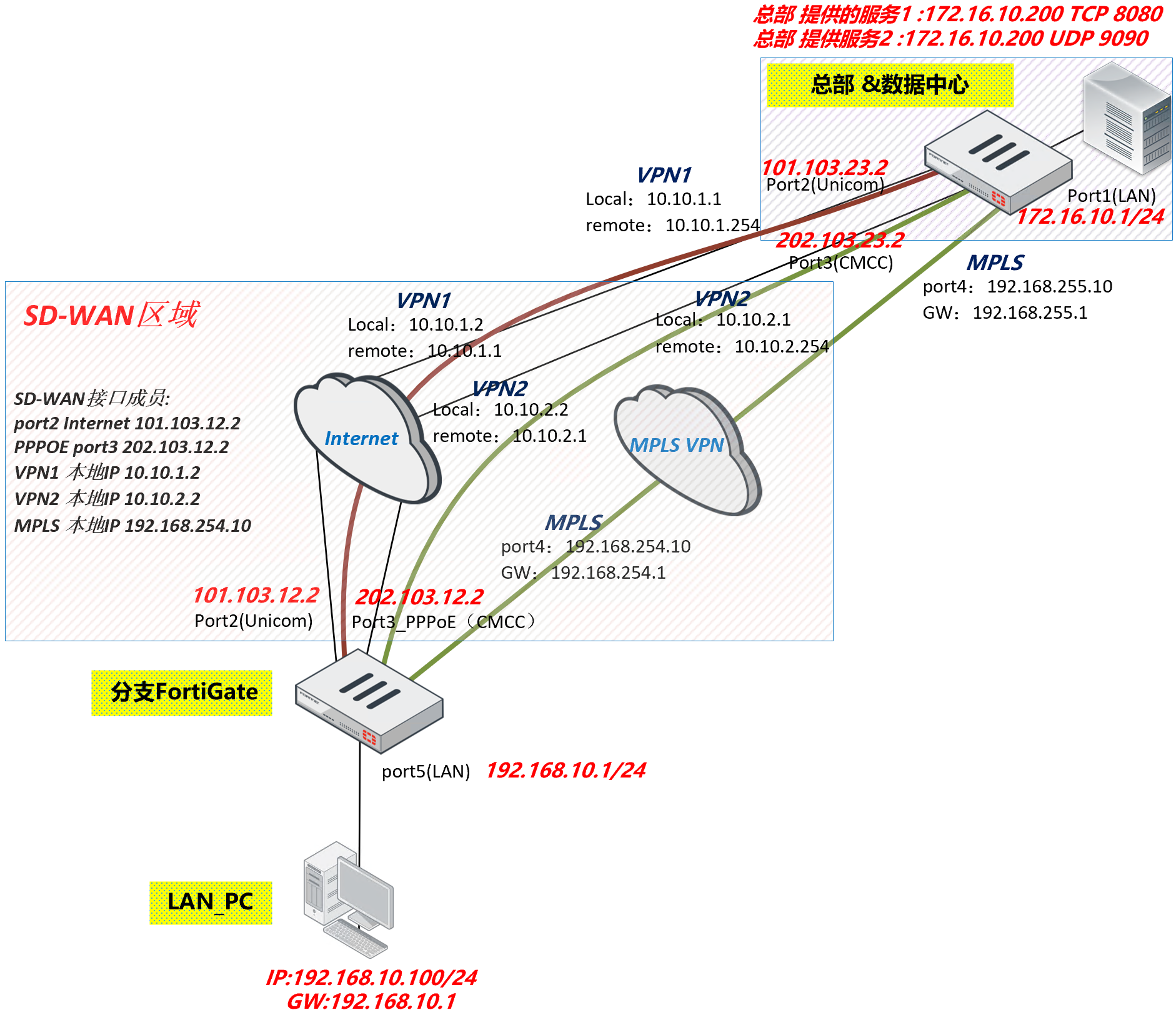
- Internet 访问:
- 分支 FortiGate 通过 2 个运营商(联通 port2、移动 PPPoE)接入 Internet,其中联通为固定 IP,移动线路为 PPPoE 线路。联通和移动线路借用出接口 IP 作为 SNAT 的源地址访问 Internet。
- 总部 FortiGate 通过 2 个运营商(联通 port2、移动 port3,均为固定 IP)接入 Internet。
- 分支 FortiGate 与总部 FortiGate 间的流量:
- 通过 MPLS 专线互联(port4)。
- 通过两条 Internet 线路上的 IPSec 隧道互联(作为 MPLS 专线的备份链路)。
- 分支 FortiGate 配置 SD-WAN,划分 2 个 SD-WAN 区域:
- 一个区域用于访问 Internet,成员为联通 port2、移动 PPPoE 接口。
- 另一个区域用于分支 FortiGate 与总部 FortiGate 间的流量,成员为两条 Internet 线路上的 IPSec 接口和 MPLS 专线接口 port4。
- 分支 FortiGate 的流量控制:
- 访问 Internet 的流量优先从联通线路(port2)转发,联通线路的质量不符合标准时,通过移动线路(PPPoE)转发。
- 访问总部 FortiGate 内网的流量优先通过 MPLS 线路(port4)转发,MPLS 线路质量不佳或中断时,优先通过联通线路上的 IPSec 隧道转发,其次通过移动线路上的 IPSec 隧道转发。
- 部署 SD-WAN 通常在一个全新的设备进行配置,如果需要加入 SD-WAN 区域的接口已经被其他配置(如防火墙策略)引用,是无法直接加入 SD-WAN 区域的。要加入 SD-WAN 区域,又不想删除关联的配置,请参考网络管理 → SD-WAN → SD-WAN 配置举例 → 将已关联接口移至 SD-WAN 区域章节。
配置步骤
基础配置
Spoke
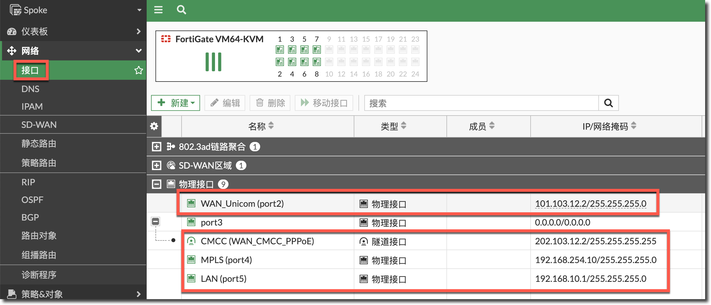
配置分支 FortiGate 2 条运营商线路的 IP、PPPoE 用户(PPPoE 请通过 CLI 配置,参考部署前注意事项 → PPPoE 接口配置章节)、MPLS 线路 IP 与内网口 IP。
PPPoE接口配置:
config system pppoe-interface
    edit "WAN_CMCC_PPPoE"
        set device "port3"
        set username "user1"
        set password xxxxxx
    next
end

固定IP接口配置:
config system interface
    edit "port2"
        set vdom "root"
        set ip 101.103.12.2 255.255.255.0
        set allowaccess ssh
        set alias "WAN_Unicom"
    next
    edit "port4"
        set vdom "root"
        set ip 192.168.254.10 255.255.255.0
        set allowaccess ssh
        set alias "MPLS"
    next
    edit "port5"
        set vdom "root"
        set ip 192.168.10.1 255.255.255.0
        set allowaccess ping https ssh http
        set alias "LAN"
    next
end
Hub
配置总部 FortiGate 2 条运营商线路的 IP、MPLS 线路 IP 与内网口 IP。
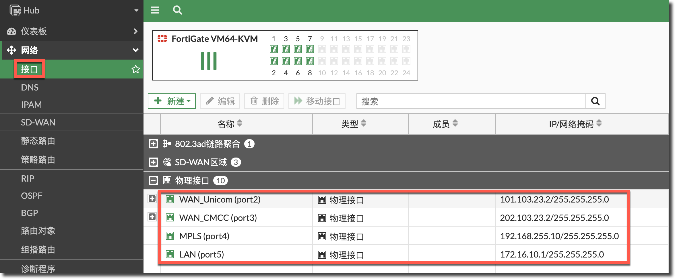
config system interface
    edit "port2"
        set vdom "root"
        set ip 101.103.23.2 255.255.255.0
        set allowaccess ssh
        set alias "WAN_Unicom"
    next
    edit "port3"
        set vdom "root"
        set ip 202.103.23.2 255.255.255.0
        set allowaccess ssh
        set alias "WAN_CMCC"
    next
    edit "port4"
        set vdom "root"
        set ip 192.168.255.10 255.255.255.0
        set allowaccess ssh
        set alias "MPLS"
    next
    edit "port5"
        set vdom "root"
        set ip 172.16.10.1 255.255.255.0
        set allowaccess ping https ssh http
        set alias "LAN"
    next
end
IPSec 配置
Spoke
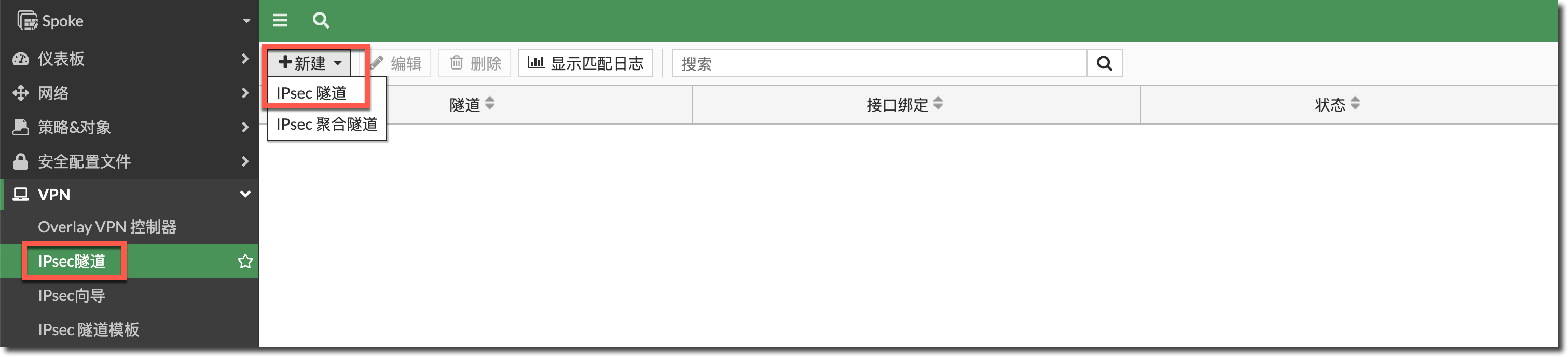
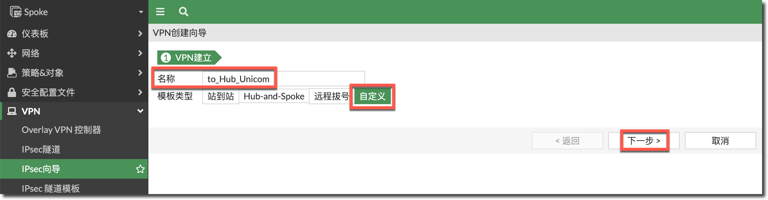
在分支(Spoke)FortiGate 上进入 VPN → IPSec 隧道页面,新建联通线路(port2)上的 IPSec 隧道,选择自定义模式,按照下图所示配置,算法默认即可。
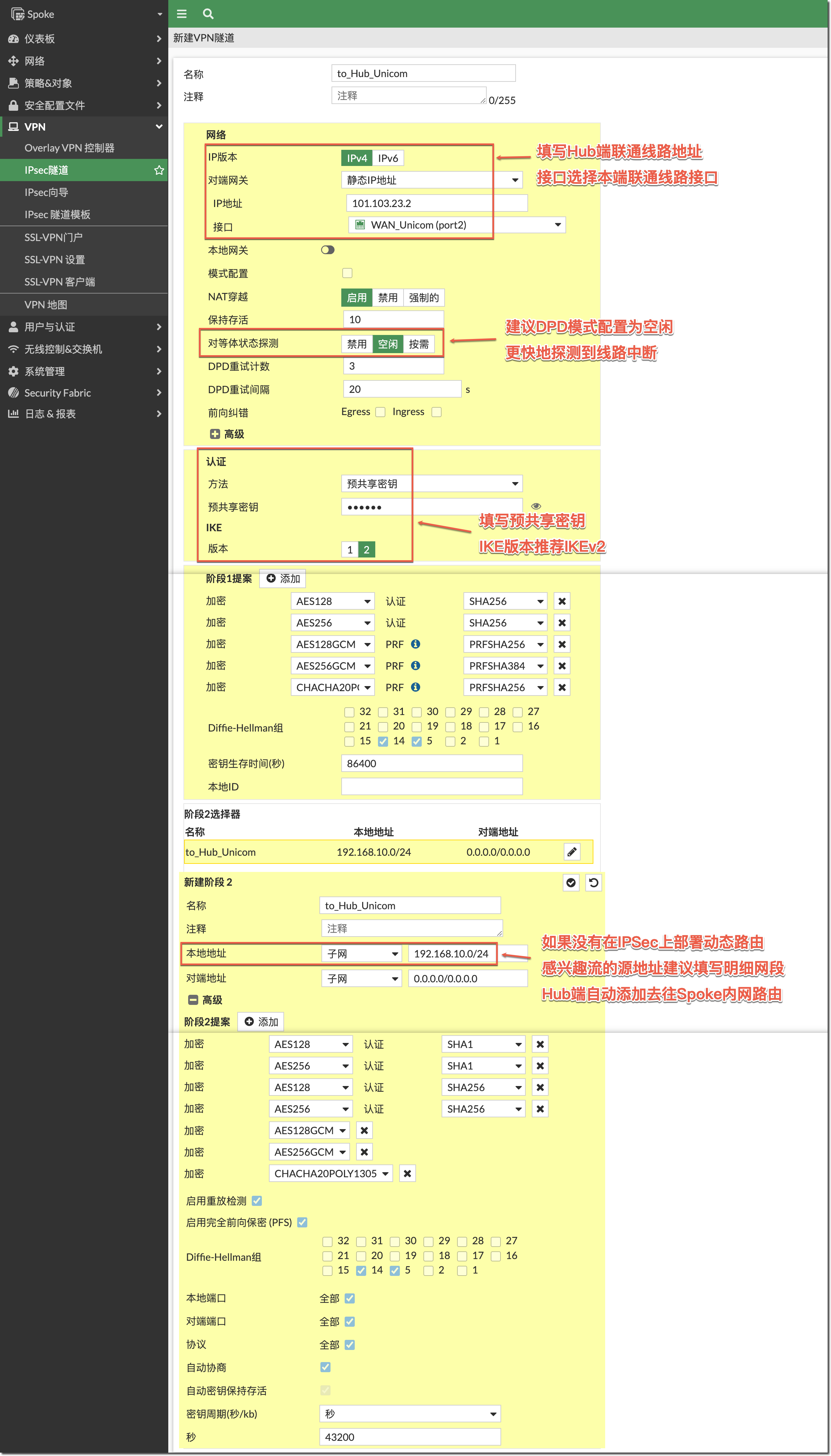
config vpn ipsec phase1-interface
    edit "to_Hub_Unicom"
        set interface "port2"
        set ike-version 2
        set peertype any
        set net-device disable
        set proposal aes128-sha256 aes256-sha256 aes128gcm-prfsha256 aes256gcm-prfsha384 chacha20poly1305-prfsha256
        set dpd on-idle
        set remote-gw 101.103.23.2
        set psksecret xxxxxx
    next
end

config vpn ipsec phase2-interface
    edit "to_Hub_Unicom"
        set phase1name "to_Hub_Unicom"
        set proposal aes128-sha1 aes256-sha1 aes128-sha256 aes256-sha256 aes128gcm aes256gcm chacha20poly1305
        set auto-negotiate enable
        set src-subnet 192.168.10.0 255.255.255.0
    next
end
新建联通线路(port2)上的 IPSec 隧道,选择自定义模式,按照下图所示配置,算法默认即可。
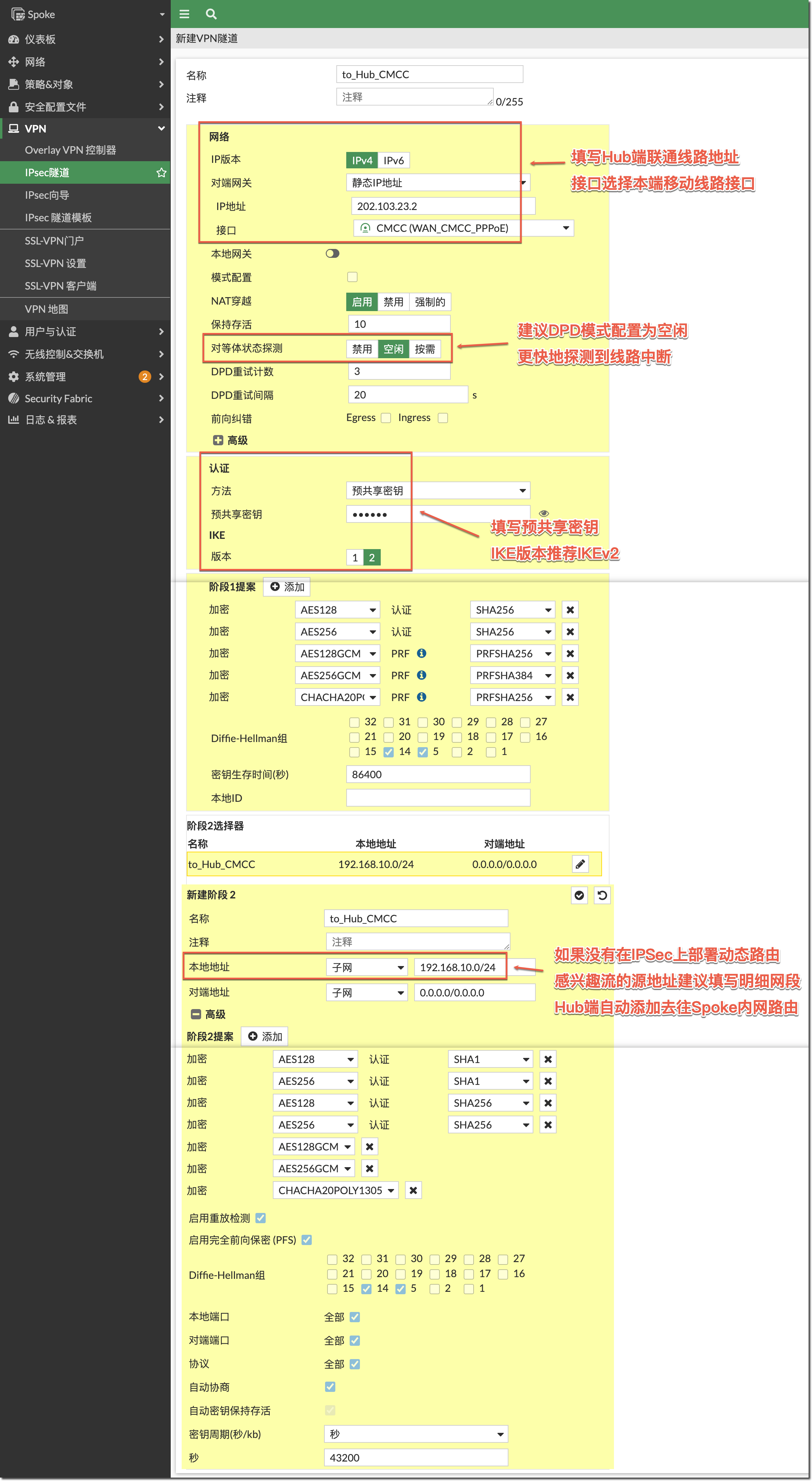
config vpn ipsec phase1-interface
    edit "to_Hub_CMCC"
        set interface "WAN_CMCC_PPPoE"
        set ike-version 2
        set peertype any
        set net-device disable
        set proposal aes128-sha256 aes256-sha256 aes128gcm-prfsha256 aes256gcm-prfsha384 chacha20poly1305-prfsha256
        set dpd on-idle
        set remote-gw 202.103.23.2
        set psksecret xxxxxx
    next
end

config vpn ipsec phase2-interface
    edit "to_Hub_CMCC"
        set phase1name "to_Hub_CMCC"
        set proposal aes128-sha1 aes256-sha1 aes128-sha256 aes256-sha256 aes128gcm aes256gcm chacha20poly1305
        set auto-negotiate enable
        set src-subnet 192.168.10.0 255.255.255.0
    next
end
Hub
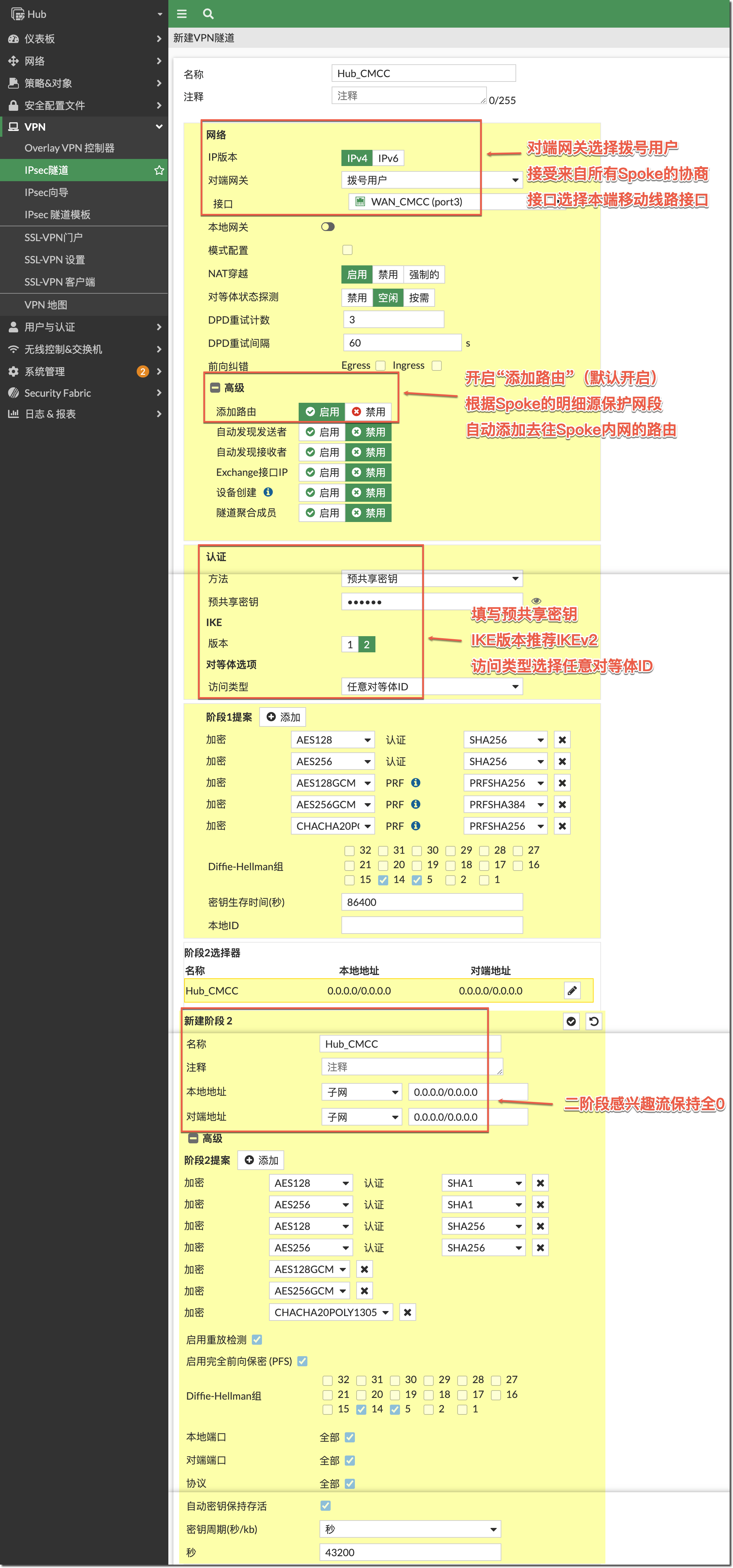
在总部(Hub)FortiGate 上进入 VPN → IPSec 隧道页面,新建联通线路(port2)上的 IPSec 隧道(拨号模式),选择自定义模式,按照下图所示配置,算法默认即可。
重要
如果 Hub 端不使用 SD-WAN 功能,请配置联通线路 IPSec add-route 添加路由的优先级为 100。优先于移动线路 IPSec 的优先级 200,当 Hub 端的 MPLS 专线中断时,优先使用联通线路主动访问 Spoke。
重要
由于 Spoke 两条线路的 IPSec 配置的源保护网段一致,Hub 端的两个拨号连接在 add-route 时会产生冲突,导致 Spoke 两条线路的两条隧道发生震荡,所以在 GUI 配置下发完成后,需要编辑二阶段接口配置,添加“set route-overlap allow”配置,如下 CLI 所示。

config vpn ipsec phase1-interface
    edit "Hub_Unicom"
        set type dynamic
        set interface "port2"
        set ike-version 2
        set peertype any
        set net-device disable
        set proposal aes128-sha256 aes256-sha256 aes128gcm-prfsha256 aes256gcm-prfsha384 chacha20poly1305-prfsha256
        set add-route enable    //确认add-route为enable,如果是disable,手动enable它//
        set dpd on-idle
        set psksecret xxxxxx
        set priority 100    //如果Hub端不配置SD-WAN,配置此项赋值add-route添加路由的优先级//
        set dpd-retryinterval 60
    next
end

config vpn ipsec phase2-interface
    edit "Hub_Unicom"
        set phase1name "Hub_Unicom"
        set proposal aes128-sha1 aes256-sha1 aes128-sha256 aes256-sha256 aes128gcm aes256gcm chacha20poly1305
        set keepalive enable
        set route-overlap allow    //重要:注意在CLI下添加此配置//
    next
end
在总部(Hub)FortiGate 上新建移动线路(port3)上的 IPSec 隧道(拨号模式),选择自定义模式,按照下图所示配置,算法默认即可。。
重要
如果 Hub 端不使用 SD-WAN 功能,请配置移动线路 IPSec add-route 添加路由的优先级为 200。次于移动线路 IPSec 的优先级 100,当 Hub 端的 MPLS 专线中断时,优先使用联通线路的 IPSec 主动访问 Spoke 内网,其次使用移动线路的 IPSec 主动访问 Spoke 内网。
重要
由于 Spoke 两条线路的 IPSec 配置的源保护网段一致,Hub 端的两个拨号连接在 add-route 时会产生冲突,导致 Spoke 两条线路的两条隧道发生震荡,所以在 GUI 配置下发完成后,需要编辑二阶段接口配置,添加“set route-overlap allow”配置,如下 CLI 所示。
config vpn ipsec phase1-interface
    edit "Hub_CMCC"
        set type dynamic
        set interface "port3"
        set ike-version 2
        set peertype any
        set net-device disable
        set proposal aes128-sha256 aes256-sha256 aes128gcm-prfsha256 aes256gcm-prfsha384 chacha20poly1305-prfsha256
        set add-route enable    //确认add-route为enable,如果是disable,手动enable它//
        set dpd on-idle
        set psksecret xxxxxx
        set priority 200    //如果Hub端不配置SD-WAN,配置此项赋值add-route添加路由的优先级//
        set dpd-retryinterval 60
    next
end

config vpn ipsec phase2-interface
    edit "Hub_CMCC"
        set phase1name "Hub_CMCC"
        set proposal aes128-sha1 aes256-sha1 aes128-sha256 aes256-sha256 aes128gcm aes256gcm chacha20poly1305
        set keepalive enable
        set route-overlap allow    //重要:注意在CLI下添加此配置//
    next
end
SD-WAN 基础配置
Spoke
进入分支 FortiGate 的网络 → SD-WAN → SD-WAN 区域页面,新建用于访问 Internet 的区域“to_Internet”(也可以直接使用预置的 SD-WAN 区域)和用于访问总部 FortiGate 内网的区域“to_Hub”。
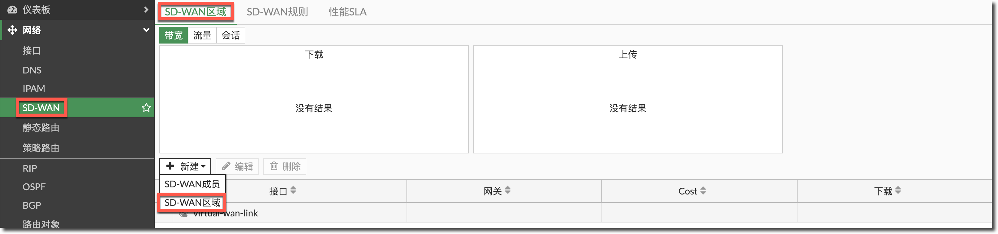
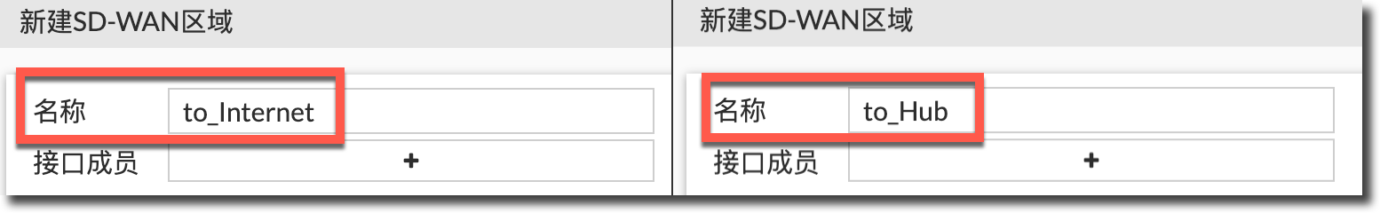
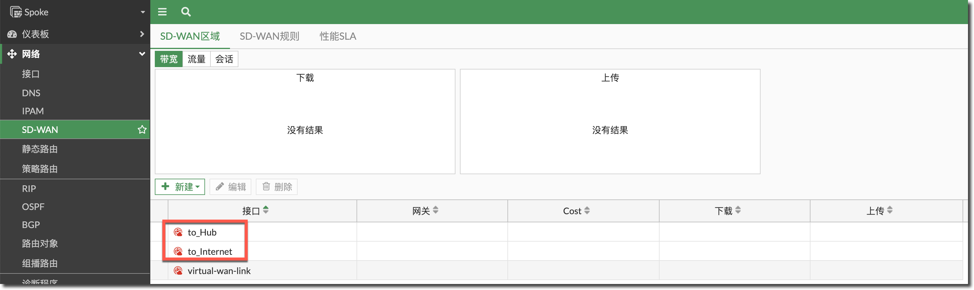
config system sdwan
    set status enable
    config zone
        edit "to_Internet"
        next
        edit "to_Hub"
        next
    end
end
在此页面新建用于访问 Internet 的 SD-WAN 成员(联通、移动线路 2 个接口)加入上步创建的 SD-WAN 区域 "to_Internet",注意 PPPoE 加入 SD-WAN 区域时不需要填写网关。
重要
如果 WAN 接口存在相关配置引用的情况下,是无法直接加入到 SD-WAN 接口成员的,可参考网络管理 → SD-WAN → SD-WAN 配置举例 → 将已关联接口移至 SD-WAN 区域章节快速将接口加入 SD-WAN 区域,并自动修改关联配置(也可选择手动将 WAN 接口的相关配置删除引用,包括策略、Link-monitor、所属区域等)。
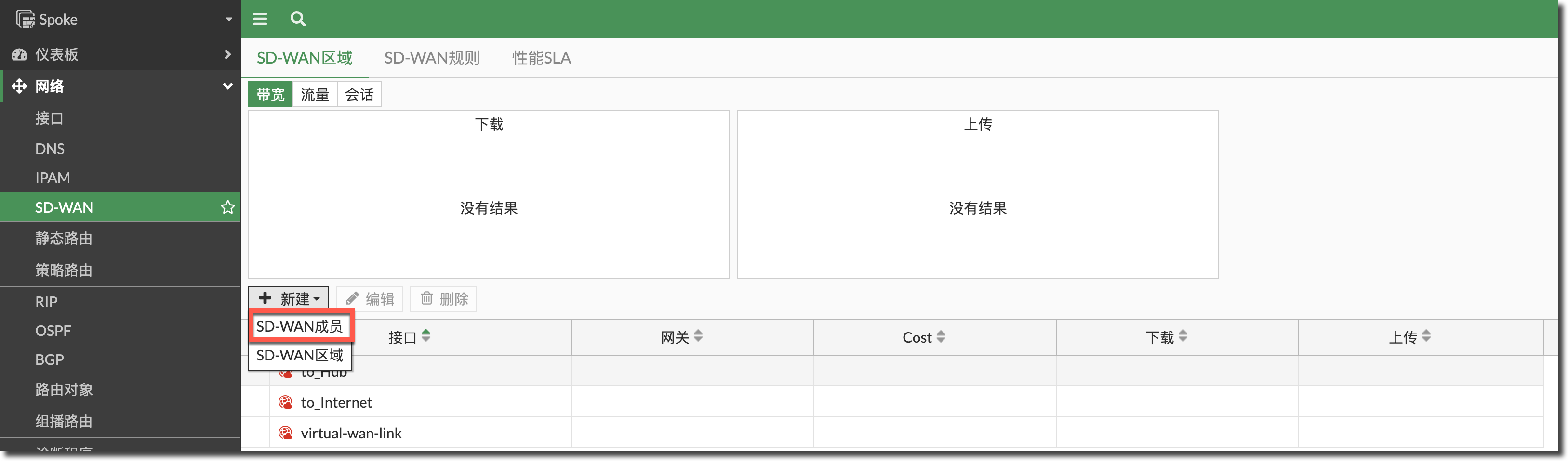
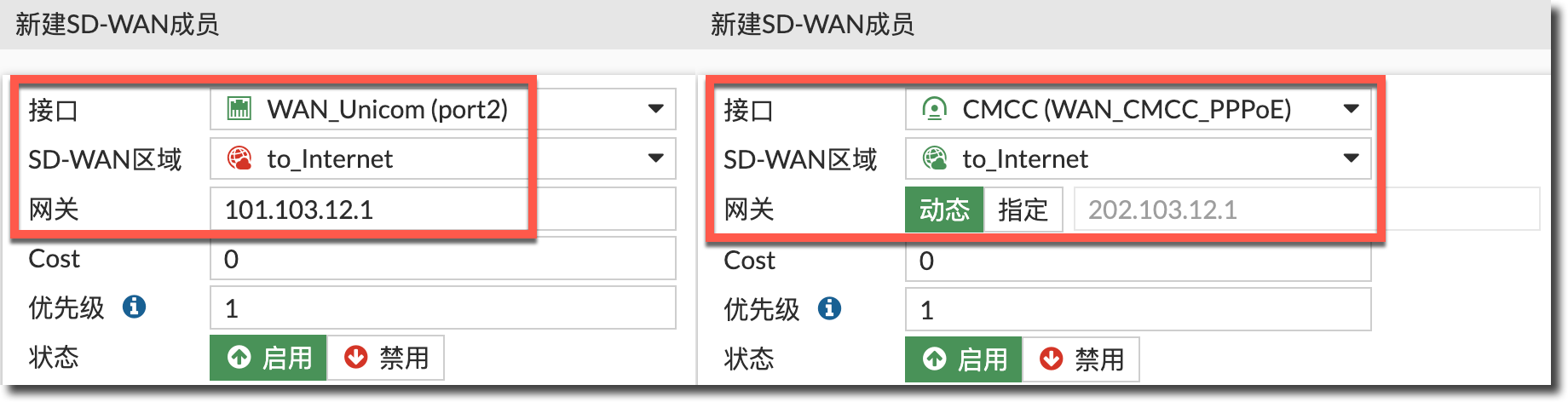
config system sdwan
    config members
        edit 1
            set interface "port2"
            set zone "to_Internet"
            set gateway 101.103.12.1
        next
        edit 2
            set interface "WAN_CMCC_PPPoE"
            set zone "to_Internet"
        next
    end
end
新建用于访问 Hub 内网的 SD-WAN 成员(两个 IPSec Tunnel 接口和 MPLS 线路接口)加入步骤 1 创建的 SD-WAN 区域 "to_Hub"。注意 IPSec Tunnel 接口加入 SD-WAN 区域时不需要填写网关。
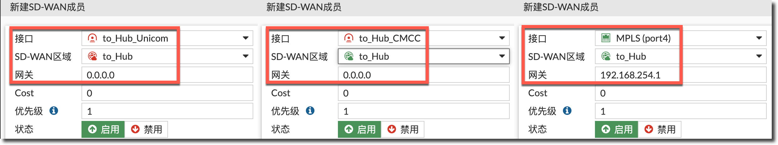
config system sdwan
    config members
        edit 3
            set interface "to_Hub_Unicom"
            set zone "to_Hub"
        next
        edit 4
            set interface "to_Hub_CMCC"
            set zone "to_Hub"
        next
        edit 5
            set interface "port4"
            set zone "to_Hub"
            set gateway 192.168.254.1
        next
    end
end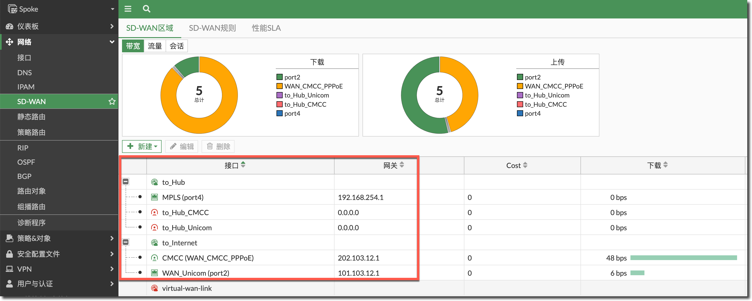
配置默认路由指向 SD-WAN 区域“to_Internet”,配置去往 Hub 端内网网段的路由指向 SD-WAN 区域“to_Hub”。
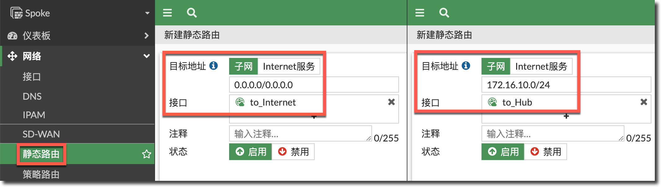
config router static
    edit 4
        set distance 1
        set sdwan-zone "to_Internet"
    next
    edit 5
        set dst 172.16.10.0 255.255.255.0
        set distance 1
        set sdwan-zone "to_Hub"
    next
end
配置防火墙策略 1,放通内网 port5(LAN)与 Hub 内网之间互相访问的流量(配置前在“系统管理 → 可见功能”中开启“多接口策略”),通常情况下内网之间的访问不需要开启 SNAT。根据需求开启 UTM 功能。
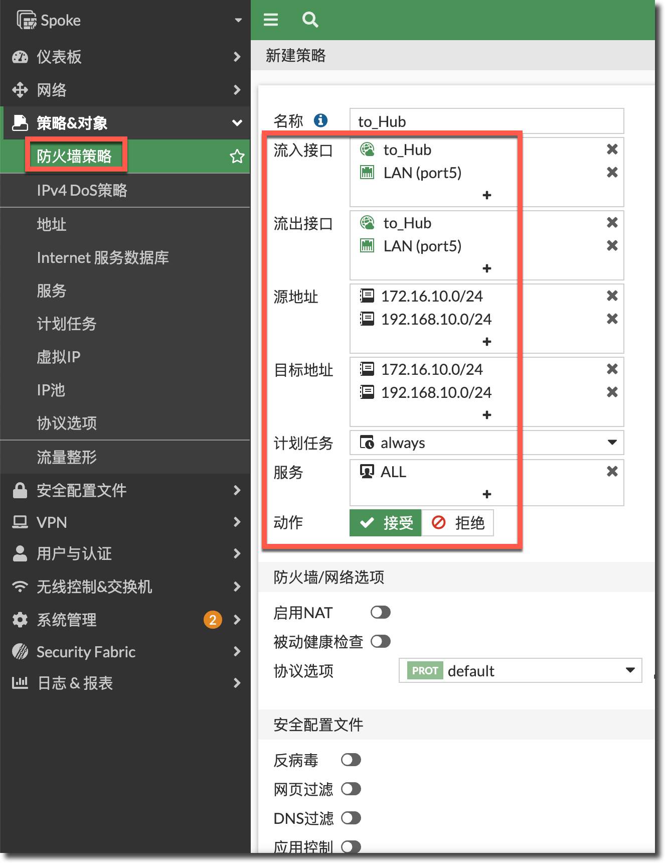
config firewall policy
    edit
        set name "to_Hub"
        set srcintf "to_Hub" "port5"
        set dstintf "to_Hub" "port5"
        set action accept
        set srcaddr "172.16.10.0/24" "192.168.10.0/24"
        set dstaddr "172.16.10.0/24" "192.168.10.0/24"
        set schedule "always"
        set service "ALL"
    next
end
配置防火墙策略 2,放通内网 port5(LAN)到 2 个运营商线路(SD-WAN 区域“to_Internet”)的 Internet 访问,并开启 SNAT(借用出接口地址)。根据需求开启 UTM 功能。
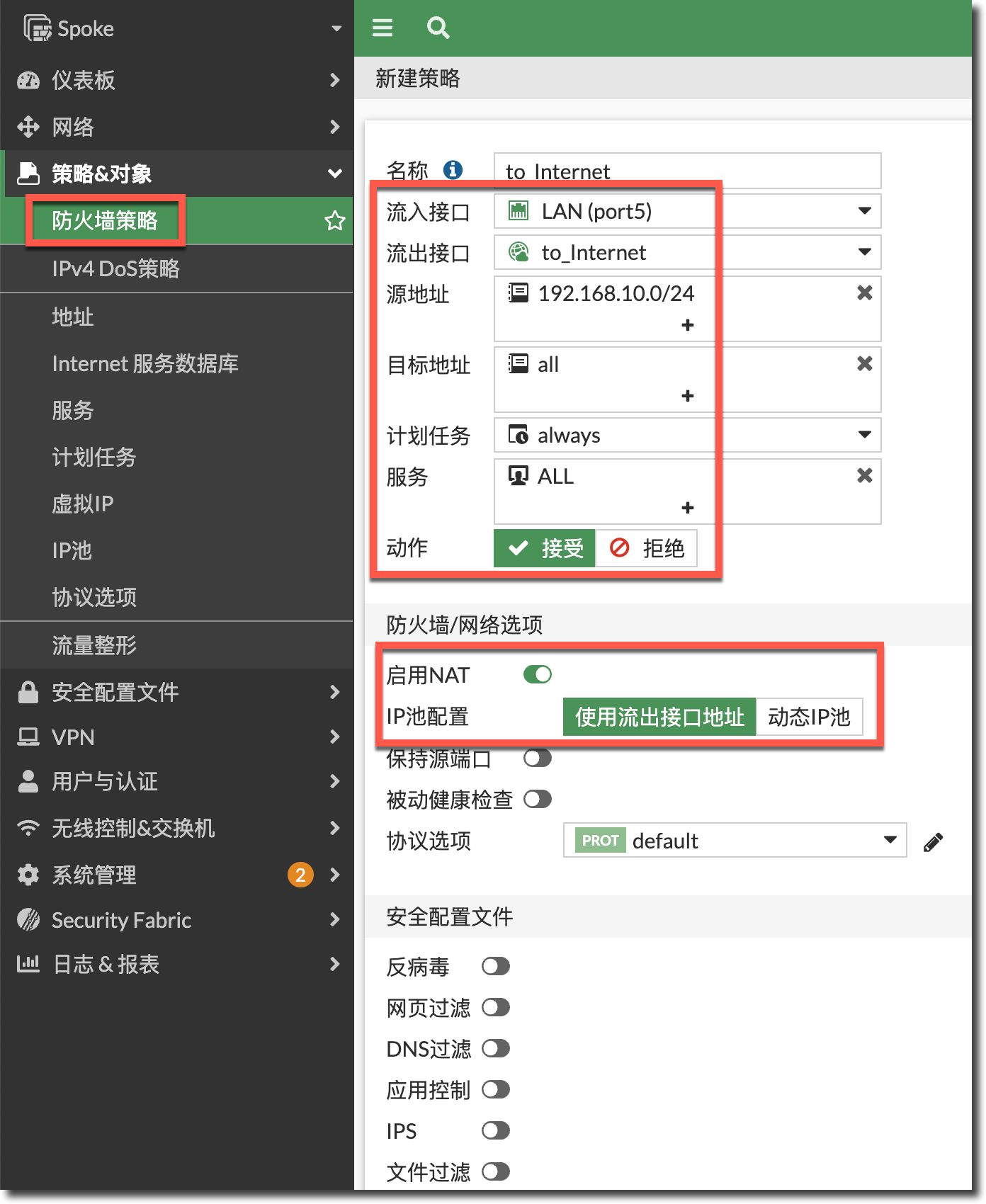
config firewall policy
    edit 2
        set name "to_Internet"
        set srcintf "port5"
        set dstintf "to_Internet"
        set action accept
        set srcaddr "192.168.10.0/24"
        set dstaddr "all"
        set schedule "always"
        set service "ALL"
        set logtraffic all
        set nat enable
    next
end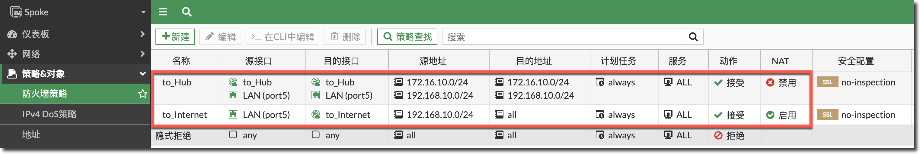
Hub
Hub 端如果需要配置 SD-WAN,可以参考 Spoke 对应的配置。
Hub 也可以不配置 SD-WAN。如果不配置 SD-WAN 选路,可以通过静态路由不同的优先级进行选路。这里我们以 Hub 端不配置 SD-WAN 为例。
配置路由:
- 指向联通线路(port2,优先级为 100)和移动线路(port3,优先级为 200)。优先从联通线路访问 Internet,联通线路 DOWN 时,从移动线路访问 Internet。
- 通过 MPLS 专线(port4)去往 Spoke 内网的路由,管理距离配置为 15(由于 IPSec add-route 添加的路由 distance 默认为 15,这里需要配置 distance 为 15,与 IPSec add-route 添加的两条路由负载,否则无法进入路由表),优先级配置为默认的 1(优先于 IPSec add-route 添加的两条路由)。
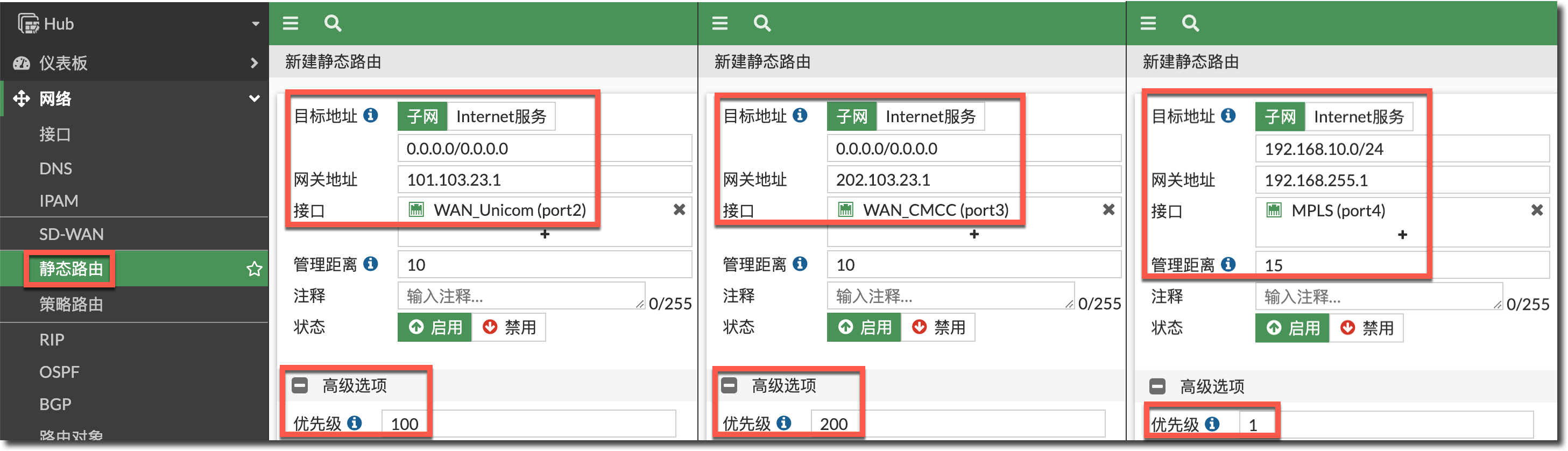
去往 Spoke 内网的路由通过 IPSec 一阶段配置中的 add-route 实现,联通线路 IPSec 自动添加的路由优先级为 100,移动线路 IPSec 自动添加的路由优先级为 200。
- Hub 内网主动访问 Spoke 内网的流量,优先从联通线路的 IPSec 访问 Spoke 内网,联通线路 IPSec DOWN 时,从移动线路的 IPSec 访问 Spoke 内网。
- Spoke 内网主动访问 Hub 内网的流量,在 Hub 的两条 IPSec 隧道中源进源出。
配置防火墙策略 1,放通内网 port5(LAN)与 Spoke 内网之间互相访问的流量,通常情况下内网之间的访问不需要开启 SNAT。根据需求开启 UTM 功能。
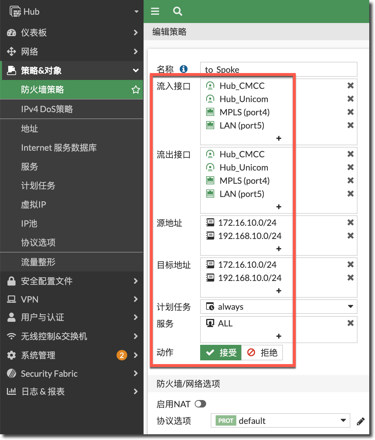
config firewall policy
    edit 1
        set name "to_Spoke"
        set srcintf "Hub_CMCC" "Hub_Unicom" "port5" "port4"
        set dstintf "Hub_CMCC" "Hub_Unicom" "port5" "port4"
        set action accept
        set srcaddr "172.16.10.0/24" "192.168.10.0/24"
        set dstaddr "172.16.10.0/24" "192.168.10.0/24"
        set schedule "always"
        set service "ALL"
    next
end
配置防火墙策略 2,放通内网 port5(LAN)到 2 个运营商线路的 Internet 访问(配置前在“系统管理 → 可见功能”中开启“多接口策略”),并开启 SNAT(借用出接口地址)。根据需求开启 UTM 功能。
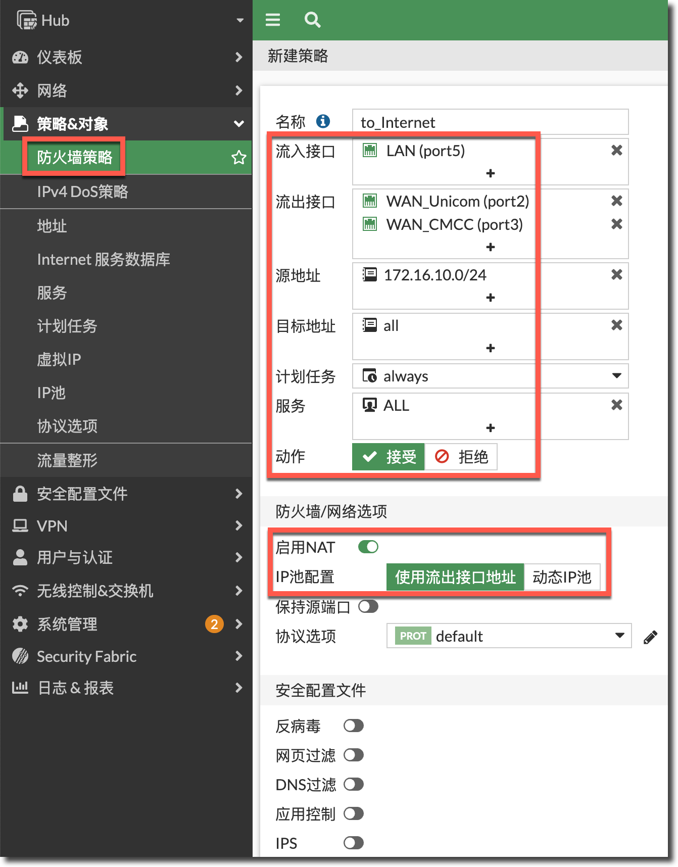
config firewall policy
    edit 2
        set name "to_Internet"
        set srcintf "port5"
        set dstintf "port2" "port3"
        set action accept
        set srcaddr "172.16.10.0/24"
        set dstaddr "all"
        set schedule "always"
        set service "ALL"
        set nat enable
    next
end
状态检查
查看 Hub 端 IPSec 隧道的建立状态,两条线路上的 IPSec 均有一个拨号连接建立成功。
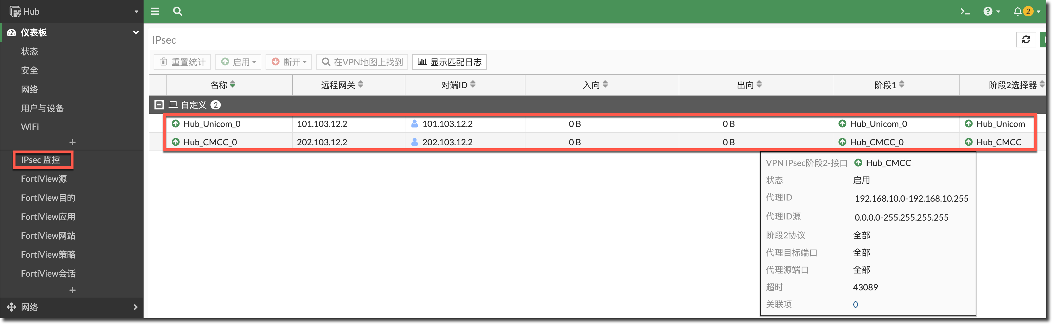
Hub # diagnose vpn tunnel list
list all ipsec tunnel in vd 0
------------------------------------------------------
......
------------------------------------------------------
name=Hub_CMCC_0 ver=2 serial=4 202.103.23.2:0->202.103.12.2:0 tun_id=202.103.12.2 tun_id6=::10.0.0.1 dst_mtu=1500 dpd-link=on weight=1
bound_if=5 lgwy=static/1 tun=intf mode=dial_inst/3 encap=none/74408 options[122a8]=npu rgwy-chg frag-rfc  run_state=0 role=primary accep0

parent=Hub_CMCC index=0
proxyid_num=1 child_num=0 refcnt=5 ilast=0 olast=0 ad=/0
stat: rxp=0 txp=0 rxb=0 txb=0
dpd: mode=on-idle on=1 idle=60000ms retry=3 count=0 seqno=6
natt: mode=none draft=0 interval=0 remote_port=0
fec: egress=0 ingress=0
proxyid=Hub_CMCC proto=0 sa=1 ref=2 serial=1 add-route
  src: 0:0.0.0.0-255.255.255.255:0
  dst: 0:192.168.10.0-192.168.10.255:0
  SA:  ref=3 options=20683 type=00 soft=0 mtu=1438 expire=42881/0B replaywin=2048
       seqno=1 esn=0 replaywin_lastseq=00000000 qat=0 rekey=0 hash_search_len=1
  life: type=01 bytes=0/0 timeout=43191/43200
  dec: spi=f6555239 esp=aes key=16 9a00355173ec08c39a49eae81d06f85c
       ah=sha1 key=20 217275e45ec62629aee93a6e786f411e9b3469c9
  enc: spi=1b2b0940 esp=aes key=16 2b84a446403798f83ff9ccc559590fac
       ah=sha1 key=20 a811652f1656b85115327fe3504fbfa29566d587
  dec:pkts/bytes=0/0, enc:pkts/bytes=0/0
  npu_flag=00 npu_rgwy=202.103.12.2 npu_lgwy=202.103.23.2 npu_selid=0 dec_npuid=0 enc_npuid=0
------------------------------------------------------
......
------------------------------------------------------
name=Hub_Unicom_0 ver=2 serial=5 101.103.23.2:0->101.103.12.2:0 tun_id=101.103.12.2 tun_id6=::10.0.0.4 dst_mtu=1500 dpd-link=on weight=1
bound_if=4 lgwy=static/1 tun=intf mode=dial_inst/3 encap=none/74408 options[122a8]=npu rgwy-chg frag-rfc  run_state=0 role=primary accep0

parent=Hub_Unicom index=0
proxyid_num=1 child_num=0 refcnt=5 ilast=0 olast=0 ad=/0
stat: rxp=0 txp=0 rxb=0 txb=0
dpd: mode=on-idle on=1 idle=60000ms retry=3 count=0 seqno=6
natt: mode=none draft=0 interval=0 remote_port=0
fec: egress=0 ingress=0
proxyid=Hub_Unicom proto=0 sa=1 ref=2 serial=4 add-route
  src: 0:0.0.0.0-255.255.255.255:0
  dst: 0:192.168.10.0-192.168.10.255:0
  SA:  ref=3 options=20683 type=00 soft=0 mtu=1438 expire=42972/0B replaywin=2048
       seqno=1 esn=0 replaywin_lastseq=00000000 qat=0 rekey=0 hash_search_len=1
  life: type=01 bytes=0/0 timeout=43189/43200
  dec: spi=f655523d esp=aes key=16 2a81dd8faebba5ead18f799af04aebdf
       ah=sha1 key=20 2769c11ebb1bb5fd25f6cafcfa830b738001857a
  enc: spi=1b2b0944 esp=aes key=16 ee9877c4c329c9d95a194859439bcbbc
       ah=sha1 key=20 11338a4d28ff61cbc71052f326d2a3719c07f323
  dec:pkts/bytes=0/0, enc:pkts/bytes=0/0
  npu_flag=00 npu_rgwy=101.103.12.2 npu_lgwy=101.103.23.2 npu_selid=4 dec_npuid=0 enc_npuid=0
查看分支(Spoke)FortiGate 路由表,默认路由在 2 个运营商线路上负载,去往 Hub 端内网的路由在两条线路的 IPSec 和 MPLS 线路上负载。
Spoke # get router info routing-table all

Routing table for VRF=0
S*      0.0.0.0/0 [1/0] via 101.103.12.1, port2, [1/0]
                  [1/0] via 202.103.12.1, WAN_CMCC_PPPoE, [1/0]
C       101.103.12.0/24 is directly connected, port2
S       172.16.10.0/24 [1/0] via to_Hub_Unicom tunnel 101.103.23.2, [1/0]
                       [1/0] via 192.168.254.1, port4, [1/0]
                       [1/0] via to_Hub_CMCC tunnel 202.103.23.2, [1/0]
C       192.168.10.0/24 is directly connected, port5
C       192.168.254.0/24 is directly connected, port4
C       202.103.12.1/32 is directly connected, WAN_CMCC_PPPoE
C       202.103.12.2/32 is directly connected, WAN_CMCC_PPPoE
查看总部(Hub)FortiGate 路由表,默认路由在 2 个运营商线路上负载,联通线路的优先级为 100,移动线路的优先级为 200;去往 Spoke 端内网的路由在两条线路的 IPSec 和 MPLS 线路上负载,MPLS 线路 IPSec 的优先级为 1,联通线路 IPSec 的优先级为 100,移动线路 IPSec 的优先级为 200。
Hub # get router info routing-table all

Routing table for VRF=0
S*      0.0.0.0/0 [10/0] via 101.103.23.1, port2, [100/0]
                  [10/0] via 202.103.23.1, port3, [200/0]
C       101.103.23.0/24 is directly connected, port2
C       172.16.10.0/24 is directly connected, port5
S       192.168.10.0/24 [15/0] via 192.168.255.1, port4, [1/0]
                        [15/0] via Hub_Unicom tunnel 101.103.12.2, [100/0]
                        [15/0] via Hub_CMCC tunnel 202.103.12.2, [200/0]
C       192.168.255.0/24 is directly connected, port4
C       202.103.23.0/24 is directly connected, port3
SD-WAN 策略配置
需求举例 1
Spoke 去往 Hub 内网的流量优先从 MPLS 专线(port4)转发,MPLS 专线中断或不满足 SLA 标准后,优先从联通线路的 IPSec 隧道转发,其次是移动线路的 IPSec 隧道。
在 Spoke 的 SD-WAN 中配置探测 Hub 端内网服务器的健康检查:
- 成员选择 MPLS 专线接口(port4)、联通线路的 IPSec 接口和移动线路的 IPSec 接口。
- 探测模式为 tcp-connect(TCP 三次握手),探测端口为 8080,指定探测的源 IP 为 Spoke 内网口 IP(需要通过 CLI 配置)。
- 开启 SLA 目标:延迟 < 250ms/抖动 < 50ms/丢包率 < 5%。
config system sdwan
    config health-check
        edit "to_Hub"
            set server "172.16.10.200"
            set protocol tcp-connect    //探测模式为TCP三次握手//
            set port 8080    //探测端口为8080//
            set source 192.168.10.1    //指定源IP为Spoke内网口地址(在IPSec感兴趣流中)//
            set members 5 4 3
            config sla
                edit 1
                    set latency-threshold 250
                    set jitter-threshold 50
                    set packetloss-threshold 5
                next
            end
        next
    end
end
查看健康检查的状态,可以看到目前 3 条去往 Hub 内网的线路都满足 SLA 标准。

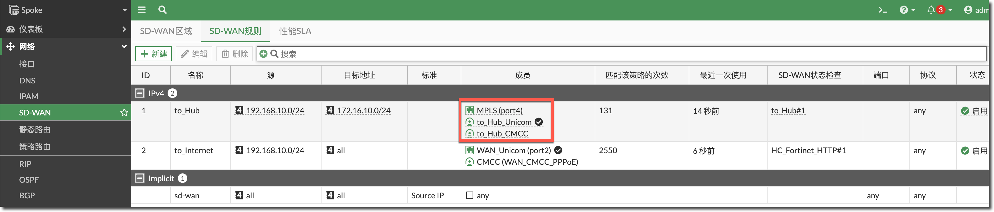
Spoke # diagnose sys sdwan health-check status to_Hub
Health Check(to_Hub):
Seq(5 port4): state(alive), packet-loss(0.000%) latency(2.661), jitter(0.672), mos(4.402), bandwidth-up(65534998), bandwidth-dw(65534999), bandwidth-bi(131069997) sla_map=0x1
Seq(4 to_Hub_CMCC): state(alive), packet-loss(0.000%) latency(108.022), jitter(17.742), mos(4.323), bandwidth-up(65534998), bandwidth-dw(65534999), bandwidth-bi(131069997) sla_map=0x1
Seq(3 to_Hub_Unicom): state(alive), packet-loss(0.000%) latency(51.611), jitter(13.453), mos(4.362), bandwidth-up(65534998), bandwidth-dw(65534999), bandwidth-bi(131069997) sla_map=0x1
新建 SD-WAN 规则 1:
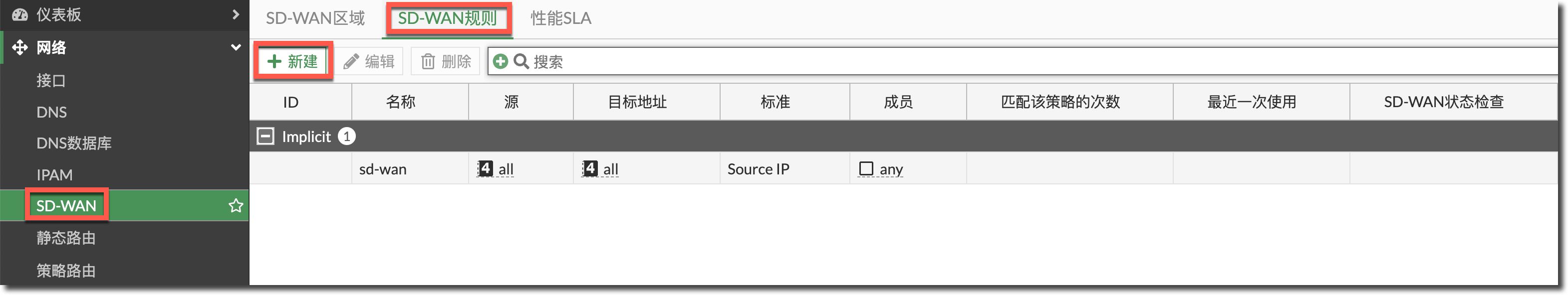
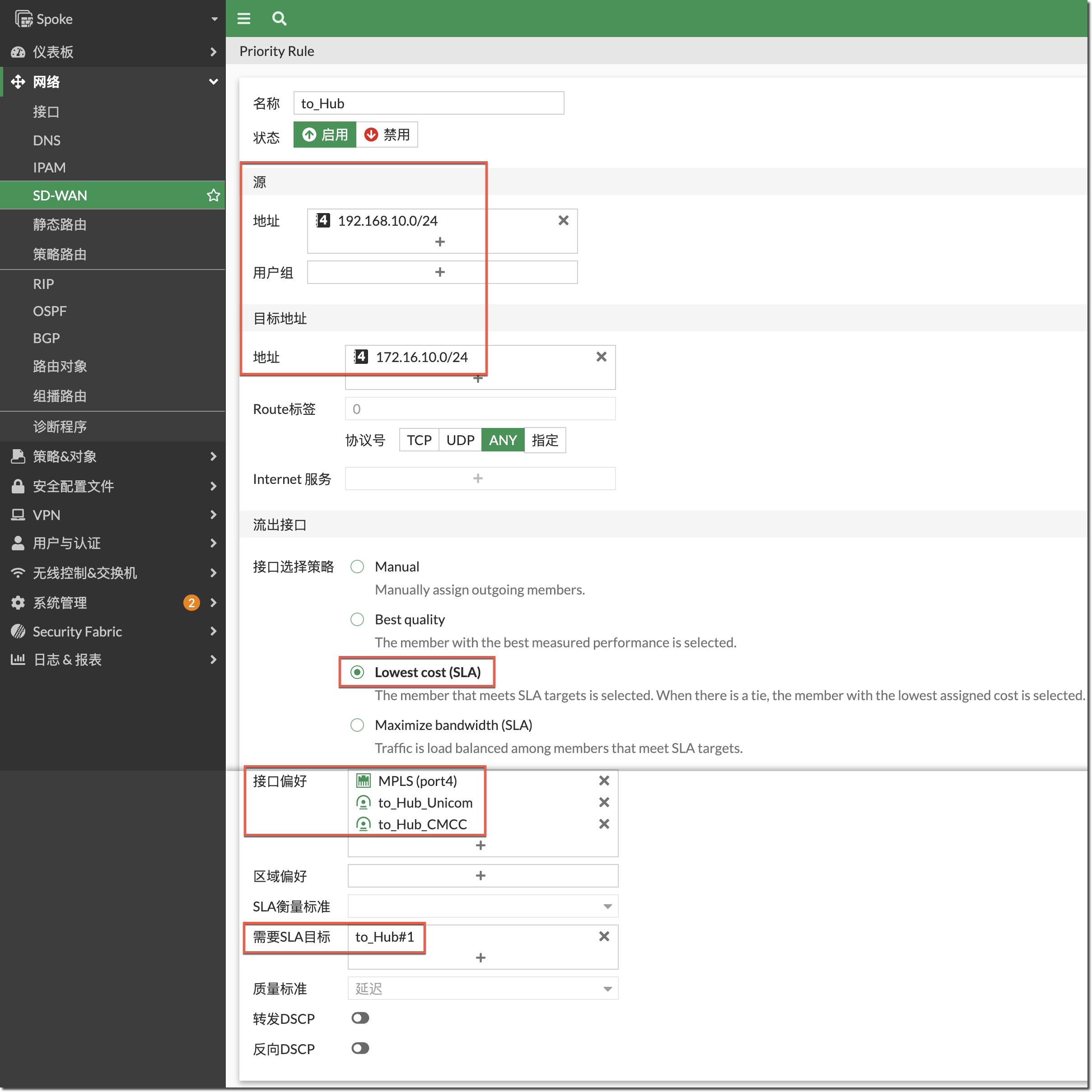
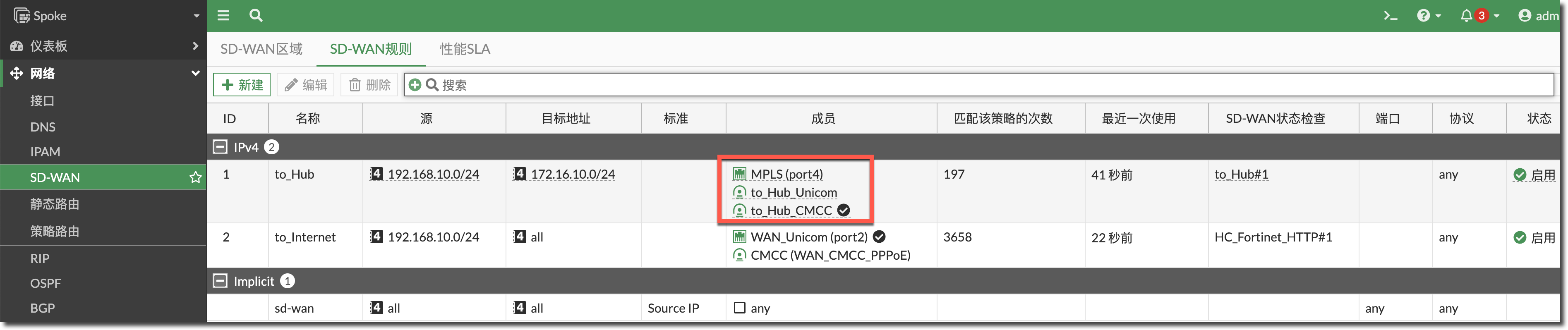
- 源地址选择 Spoke 内网网段;目标地址为 Hub 内网网段。
- 接口选择策略:选择 Lowest Cost (SLA),Spoke 内部访问 Hub 内网的流量优先从满足 SLA 标准(延迟 < 250ms/抖动 < 50ms/丢包率 < 5%)的线路转发。如果 3 条线路都满足 SLA 标准,则优先从接口偏好中靠前的接口转发。
- 接口偏好:选择 MPLS 专线接口(port4)、联通线路 IPSec 接口与移动线路 IPSec 接口。MPLS 专线接口(port4)排序在前,其次是联通线路 IPSec 接口,最后是移动线路 IPSec 接口。
- 需要的 SLA 目标:选择上步创建的 SLA 目标(延迟 < 250ms/抖动 < 50ms/丢包率 < 5%)。
config system sdwan
    config service
        edit 1
            set name "to_Hub"
            set mode sla
            set dst "172.16.10.0/24"
            set src "192.168.10.0/24"
            config sla
                edit "to_Hub"
                    set id 1
                next
            end
            set priority-members 5 3 4
        next
    end
end
查看上步创建的 SD-WAN 规则目前的选路状态,由于目前 3 条去往 Hub 内网的线路均满足 SLA 目标,所以选择接口偏好配置中靠前的 MPLS 线路接口(port4)。
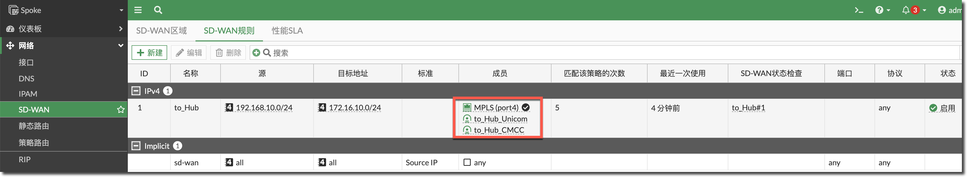
Spoke # diagnose sys sdwan service 1

Service(1): Address Mode(IPV4) flags=0x200 use-shortcut-sla
 Tie break: cfg
  Gen(1), TOS(0x0/0x0), Protocol(0: 1->65535), Mode(sla), sla-compare-order
  Members(3):
    1: Seq_num(5 port4), alive, sla(0x1), gid(0), cfg_order(0), local cost(0), selected    //优先走MPLS专线接口//
    2: Seq_num(3 to_Hub_Unicom), alive, sla(0x1), gid(0), cfg_order(1), local cost(0), selected
    3: Seq_num(4 to_Hub_CMCC), alive, sla(0x1), gid(0), cfg_order(2), local cost(0), selected
  Src address(1):
        192.168.10.0-192.168.10.255

  Dst address(1):
        172.16.10.0-172.16.10.255
查看 SD-WAN 规则对应的策略路由状态,出接口优先选择 MPLS 线路接口(port4)。
Spoke # diagnose firewall proute list
list route policy info(vf=root):

id=2134835201(0x7f3f0001) vwl_service=1(to_Hub) vwl_mbr_seq=5 3 4 dscp_tag=0xfc 0xfc flags=0x0 tos=0x00 tos_mask=0x00 protocol=0 sport=0-65535 iif=0(any) dport=1-65535 path(3) oif=6(port4) oif=22(to_Hub_Unicom) oif=23(to_Hub_CMCC)    //优先从MPLS线路接口转发//
source(1): 192.168.10.0-192.168.10.255
destination(1): 172.16.10.0-172.16.10.255
hit_count=5 last_used=2023-12-21 16:02:01
需求举例 2
Spoke 内部访问 Internet 的流量优先从满足 SLA 标准(延迟 < 250ms/抖动 < 50ms/丢包率 < 5%)的线路转发。如果两条 Internet 线路都满足 SLA 标准,则优先从联通线路转发。
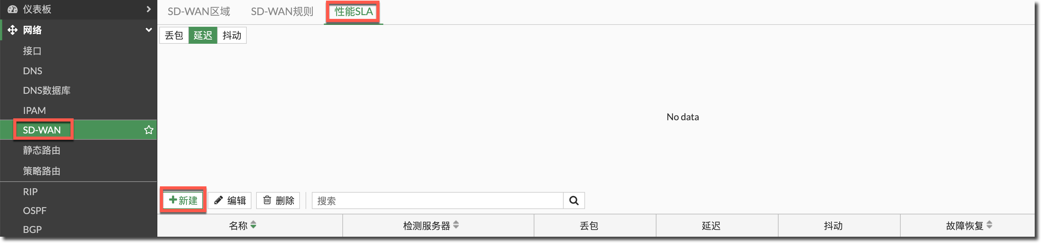
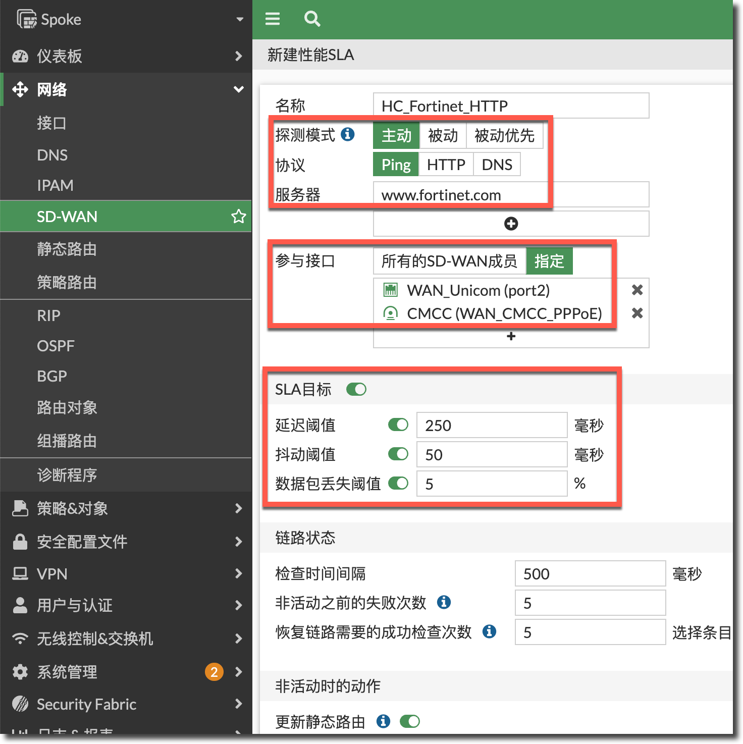
在 Spoke 的 SD-WAN 中配置探测 Internet 某个网站的 HTTP 健康检查,成员选择联通(port2)和移动(PPPoE)线路,开启 SLA 目标:延迟 < 250ms/抖动 < 50ms/丢包率 < 5%。
config system sdwan
    config health-check
        edit "HC_Fortinet_HTTP"
            set server "www.fortinet.com"
            set members 1 2
            config sla
                edit 1
                    set latency-threshold 250
                    set jitter-threshold 50
                    set packetloss-threshold 5
                next
            end
        next
    end
end
查看健康检查的状态,可以看到目前两条 Internet 线路都满足 SLA 标准。
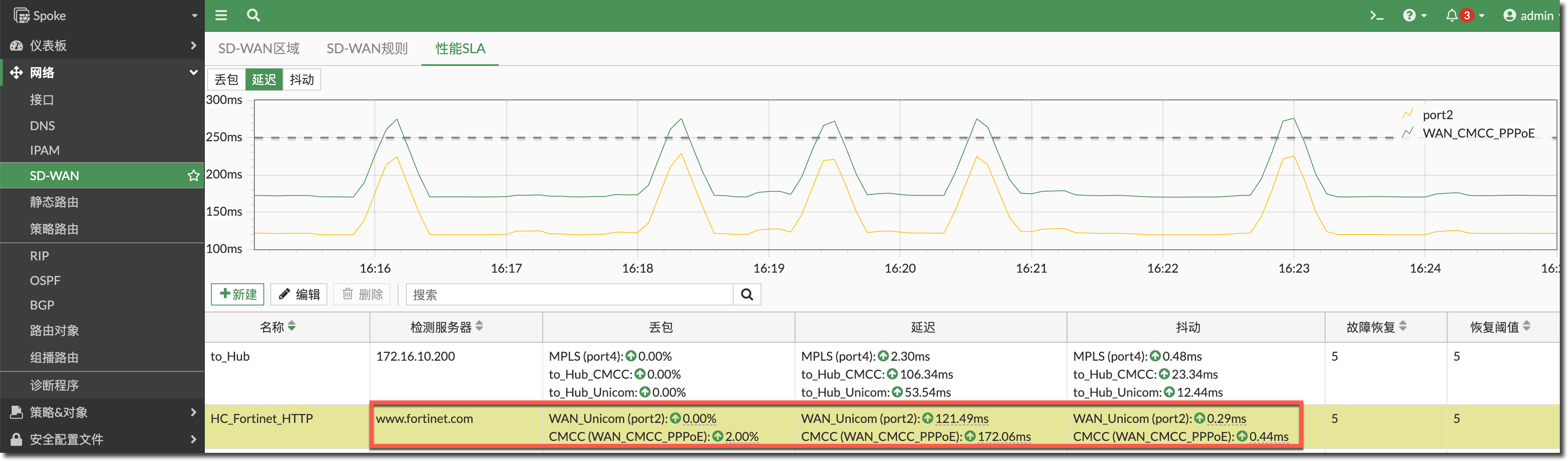
Spoke # diagnose sys sdwan health-check status HC_Fortinet_HTTP
Health Check(HC_Fortinet_HTTP):
Seq(1 port2): state(alive), packet-loss(1.000%) latency(115.769), jitter(0.618), mos(4.339), bandwidth-up(65534995), bandwidth-dw(65534996), bandwidth-bi(131069991) sla_map=0x1
Seq(2 WAN_CMCC_PPPoE): state(alive), packet-loss(2.000%) latency(166.407), jitter(0.782), mos(4.269), bandwidth-up(65534996), bandwidth-dw(65534997), bandwidth-bi(131069993) sla_map=0x1
新建 SD-WAN 规则 2:
- 源地址选择内网网段;目标地址为 all。
- 接口选择策略:选择 Lowest Cost (SLA),Spoke 内部访问 Internet 的流量优先从满足 SLA 标准(延迟 < 250ms/抖动 < 50ms/丢包率 < 5%)的线路转发。如果两条 Internet 线路都满足 SLA 标准,则优先从接口偏好中靠前的接口转发。
- 接口偏好:选择联通线路接口(port2)与移动线路接口(PPPoE),联通线路接口排序在前。
- 需要 SLA 目标:选择上步创建的 SLA 目标(延迟 < 250ms/抖动 < 50ms/丢包率 < 5%)。
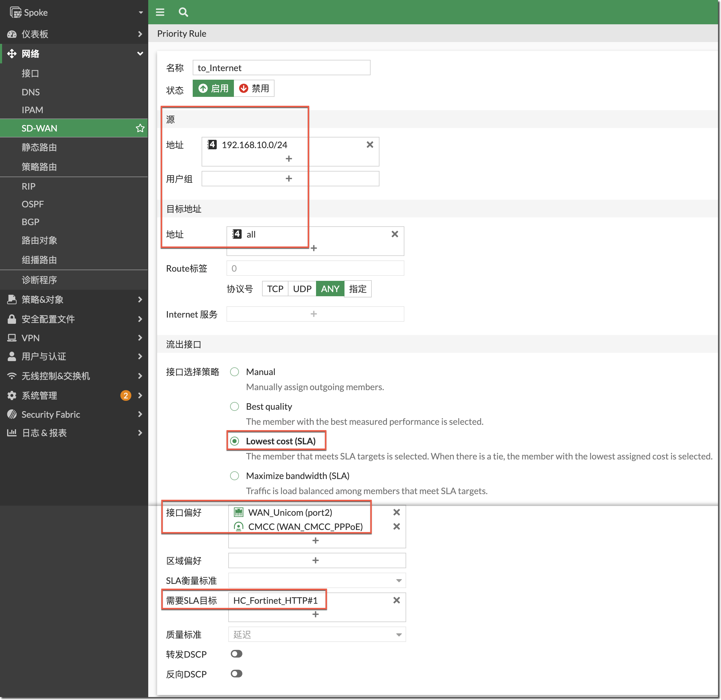
config system sdwan
    config service
        edit 2
            set name "to_Internet"
            set mode sla
            set dst "all"
            set src "192.168.10.0/24"
            config sla
                edit "HC_Fortinet_HTTP"
                    set id 1
                next
            end
            set priority-members 1 2
        next
    end
end
查看上步创建的 SD-WAN 规则目前的选路状态,由于目前两条 Internet 线路均满足 SLA 目标,所以选择接口偏好配置中靠前的联通线路(port2)。
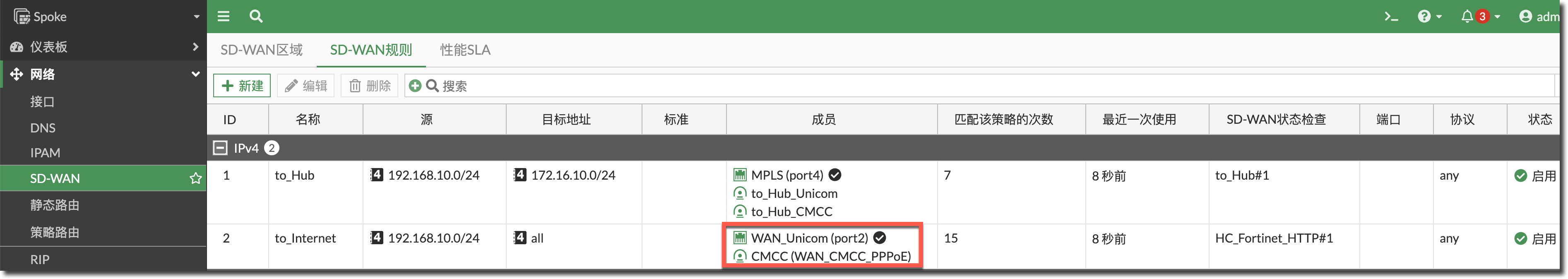
Spoke # diagnose sys sdwan service 2

Service(2): Address Mode(IPV4) flags=0x200 use-shortcut-sla
 Tie break: cfg
  Gen(1), TOS(0x0/0x0), Protocol(0: 1->65535), Mode(sla), sla-compare-order
  Members(2):
    1: Seq_num(1 port2), alive, sla(0x1), gid(0), cfg_order(0), local cost(0), selected    //联通线路(port2)优先//
    2: Seq_num(2 WAN_CMCC_PPPoE), alive, sla(0x1), gid(0), cfg_order(1), local cost(0), selected
  Src address(1):
        192.168.10.0-192.168.10.255

  Dst address(1):
        0.0.0.0-255.255.255.255
结果验证
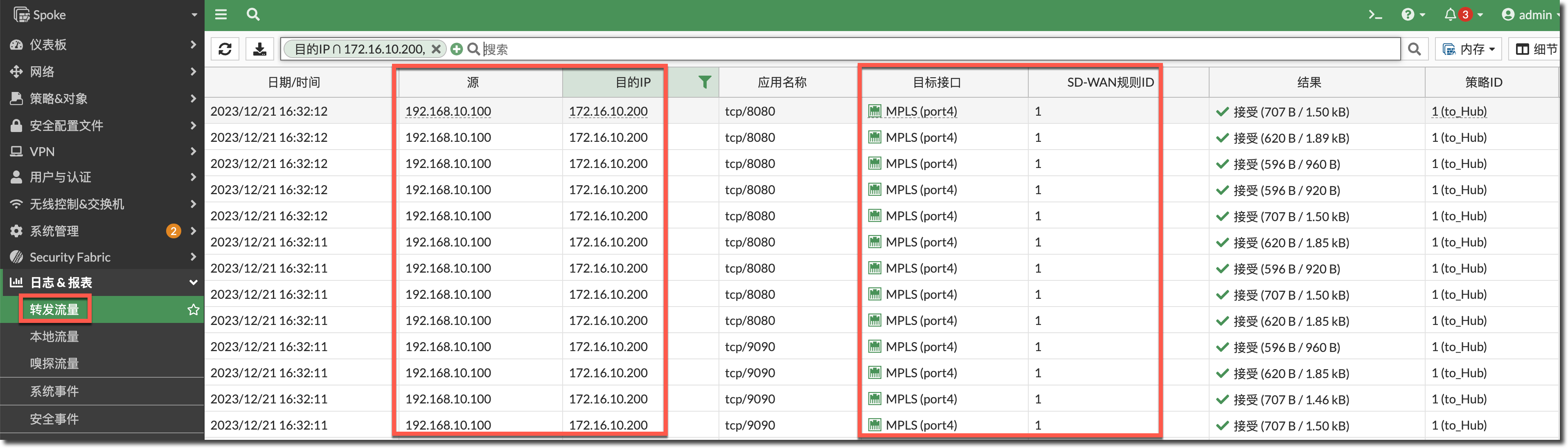
Spoke 访问 Hub
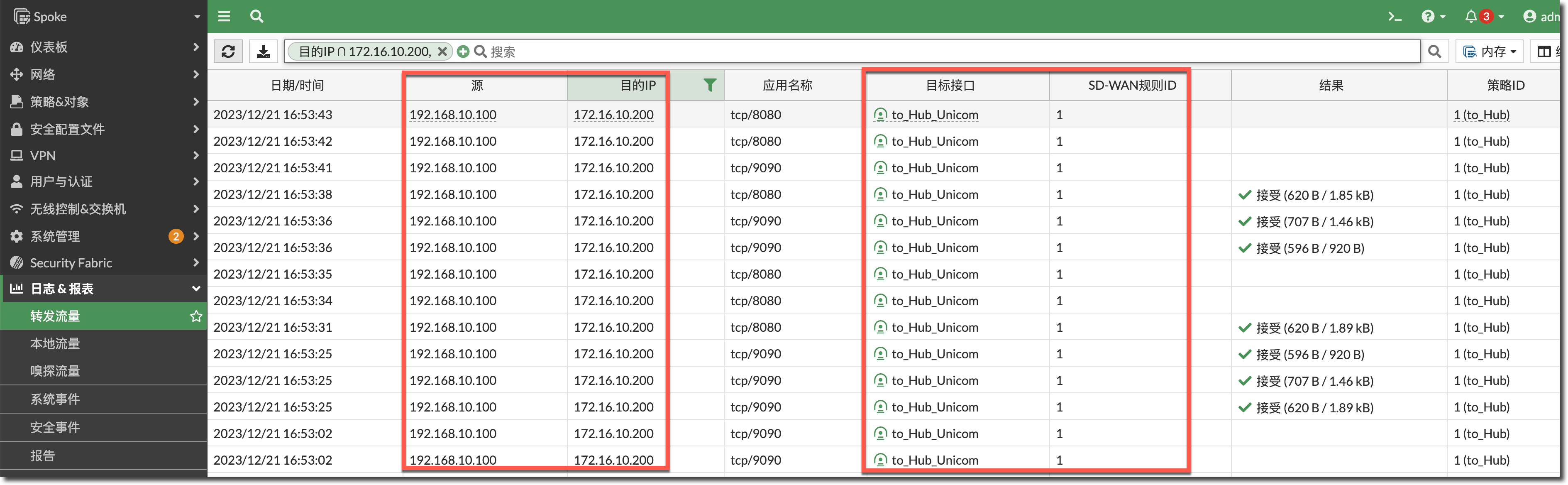
使用 Spoke 内网 PC 客户端访问 Hub 端的业务,流量可以正确的从 MPLS 线路接口(port4)转发。
模拟 MPLS 线路(port4)的健康检查的丢包率增加到 8%。
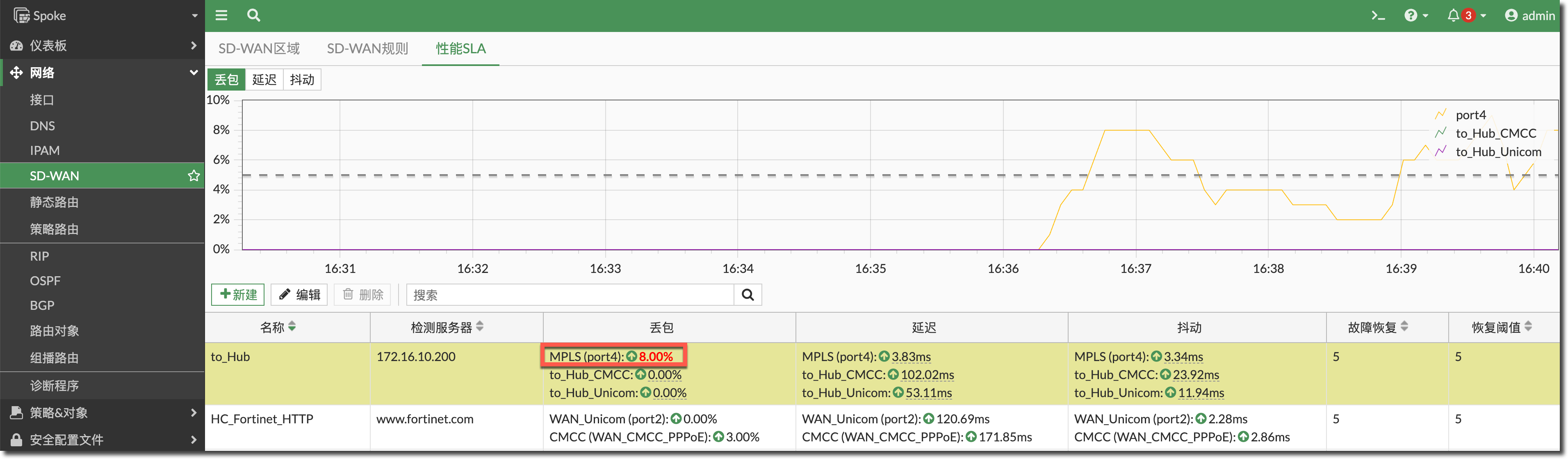
Spoke # diagnose sys sdwan health-check status to_Hub
Health Check(to_Hub):
Seq(5 port4): state(alive), packet-loss(8.000%) latency(2.444), jitter(0.530), mos(4.399), bandwidth-up(65534998), bandwidth-dw(65534999), bandwidth-bi(131069997) sla_map=0x0
Seq(4 to_Hub_CMCC): state(alive), packet-loss(0.000%) latency(106.955), jitter(26.069), mos(4.295), bandwidth-up(65534998), bandwidth-dw(65534999), bandwidth-bi(131069997) sla_map=0x1
Seq(3 to_Hub_Unicom): state(alive), packet-loss(0.000%) latency(57.014), jitter(16.204), mos(4.356), bandwidth-up(65534998), bandwidth-dw(65534999), bandwidth-bi(131069997) sla_map=0x1
查看 SD-WAN 规则 1 的选路优先选择联通线路 IPSec 接口去往 Hub 内网。
Spoke # diagnose sys sdwan service 1

Service(1): Address Mode(IPV4) flags=0x200 use-shortcut-sla
 Tie break: cfg
  Gen(22), TOS(0x0/0x0), Protocol(0: 1->65535), Mode(sla), sla-compare-order
  Members(3):
    1: Seq_num(3 to_Hub_Unicom), alive, sla(0x1), gid(0), cfg_order(1), local cost(0), selected  //优先选择满足SLA线路中配置靠前的线路//
    2: Seq_num(4 to_Hub_CMCC), alive, sla(0x1), gid(0), cfg_order(2), local cost(0), selected
    3: Seq_num(5 port4), alive, sla(0x0), gid(0), cfg_order(0), local cost(0), selected    //MPLS线路不满足SLA目标,被移至转发顺序最后//
  Src address(1):
        192.168.10.0-192.168.10.255

  Dst address(1):
        172.16.10.0-172.16.10.255
再次使用 Spoke 内网 PC 客户端访问 Hub 端的业务,流量开始从联通线路 IPSec 接口转发。
模拟联通线路 IPSec 隧道健康检查的延迟增加到 300ms。
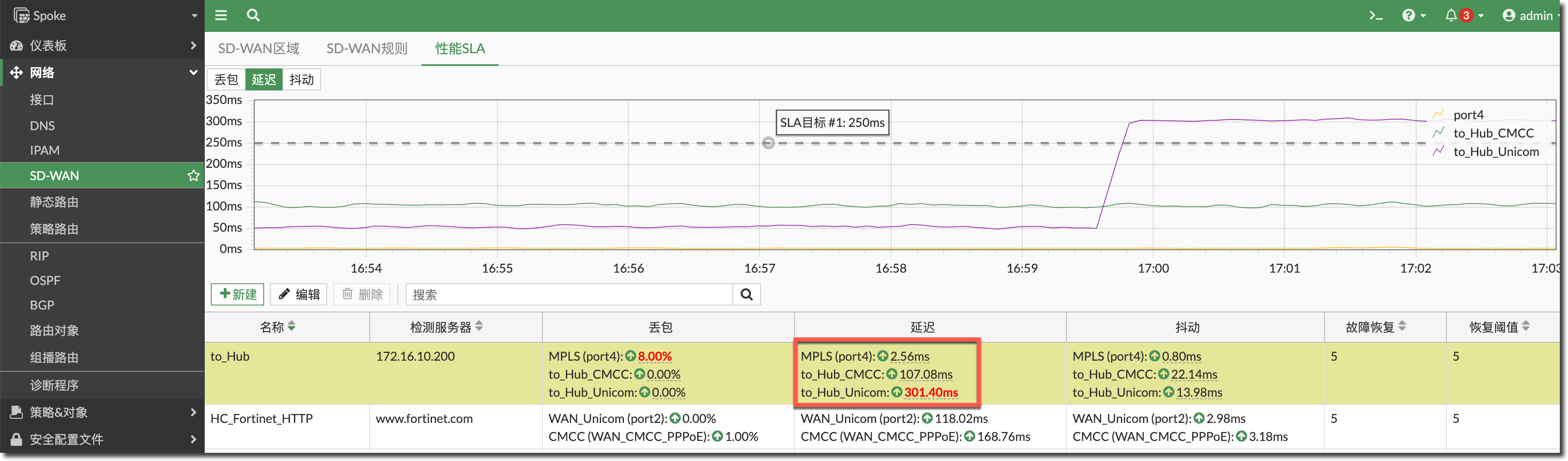
Spoke # diagnose sys sdwan health-check status to_Hub
Health Check(to_Hub):
Seq(5 port4): state(alive), packet-loss(8.000%) latency(2.540), jitter(0.578), mos(4.399), bandwidth-up(65534998), bandwidth-dw(65534999), bandwidth-bi(131069997) sla_map=0x0
Seq(4 to_Hub_CMCC): state(alive), packet-loss(0.000%) latency(106.433), jitter(17.167), mos(4.325), bandwidth-up(65534998), bandwidth-dw(65534999), bandwidth-bi(131069997) sla_map=0x1
Seq(3 to_Hub_Unicom): state(alive), packet-loss(0.000%) latency(303.372), jitter(15.259), mos(3.635), bandwidth-up(65534998), bandwidth-dw(65534999), bandwidth-bi(131069997) sla_map=0x0
查看 SD-WAN 规则 1 的选路优先选择移动线路 IPSec 接口去往 Hub 内网。
Spoke # diagnose sys sdwan service 1

Service(1): Address Mode(IPV4) flags=0x200 use-shortcut-sla
 Tie break: cfg
  Gen(33), TOS(0x0/0x0), Protocol(0: 1->65535), Mode(sla), sla-compare-order
  Members(3):
    1: Seq_num(4 to_Hub_CMCC), alive, sla(0x1), gid(0), cfg_order(2), local cost(0), selected    //优先从移动线路IPSec隧道转发//
    2: Seq_num(5 port4), alive, sla(0x0), gid(0), cfg_order(0), local cost(0), selected    //MPLS线路不满足SLA目标//
    3: Seq_num(3 to_Hub_Unicom), alive, sla(0x0), gid(0), cfg_order(1), local cost(0), selected    //联通线路IPSec隧道不满足SLA目标//
  Src address(1):
        192.168.10.0-192.168.10.255

  Dst address(1):
        172.16.10.0-172.16.10.255
对应的 SD-WAN 线路切换系统日志。
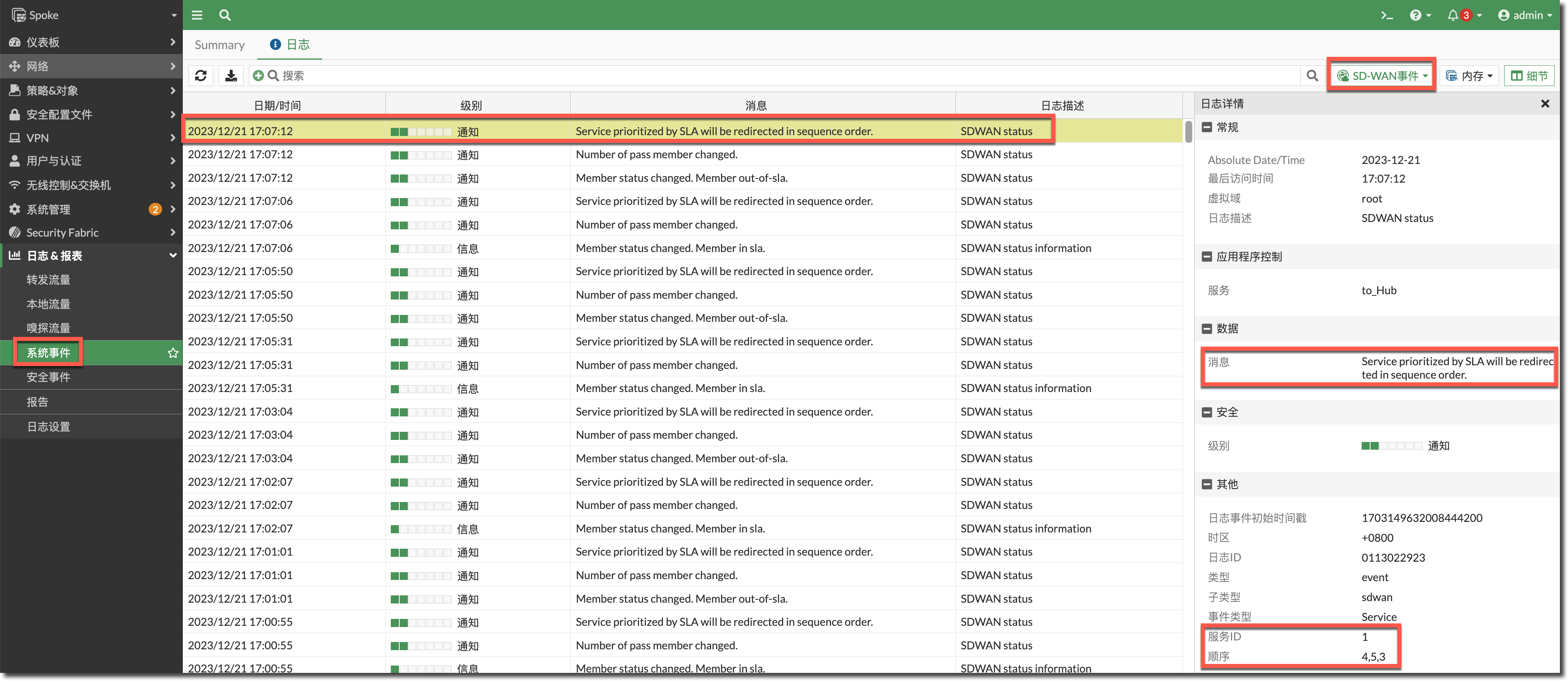
date=2023-12-21 time=17:07:12 eventtime=1703149632008444112 tz="+0800" logid="0113022923" type="event" subtype="sdwan" level="notice" vd="root" logdesc="SDWAN status" eventtype="Service" serviceid=1 service="to_Hub" seq="4,5,3" msg="Service prioritized by SLA will be redirected in sequence order."再次使用 Spoke 内网 PC 客户端访问 Hub 端的业务,流量开始从移动线路 IPSec 接口转发。
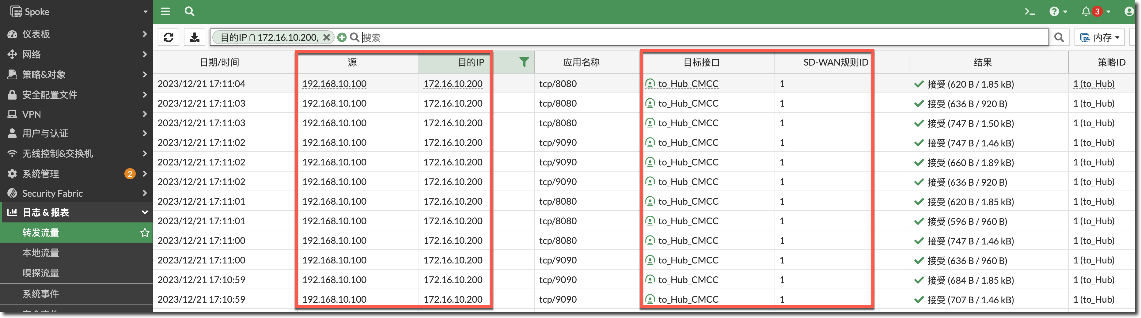
Spoke 访问 Internet
测试结果请参考 Spoke 访问 Hub 内网,线路可以根据健康检查结果是否满 SLA 目标正常切换,这里不再赘述。
注意事项
默认配置下,当 Internet 线路(有 SNAT)SD-WAN 选路出现变化后,已有的会话不会立即切换到新链路上,只有线路切换后新创建的会话会建立在新的线路上,如果想在 SD-WAN 线路切换后让已有会话立刻失效,需要使用如下命令(可能会增加 CPU 消耗,谨慎开启)。
重要
默认配置下的 SNAT 场景,即使转发流量的 SD-WAN 成员的健康检查变为 dead,只要该线路仍然存在路由(可能关闭了
update-static-route),已有的旧会话仍然不会切换到其他线路。config system global set snat-route-change enable //默认为disable// end默认配置下,当 VPN 或专线线路(无 SNAT)SD-WAN 选路出现变化后,已有的会话会立即切换到新链路上,如果想在 SD-WAN 线路切换后让已有会话保持在原来的线路上,只有新会话创建在新线路上,需要在对应 VPN 接口或专线接口上使用如下命令。
config system interface
    edit "to_Hub_Unicom"
        set preserve-session-route enable    //默认为disable//
    next
end
如何设置
add-route功能添加的路由优先级(priority)和管理距离(distance)?开启add-route后,默认添加的路由优先级为 1,管理距离为 15,如果要自定义路由优先级或管理距离,请参考如下配置(注意只有拨号模式的 IPSec 可以使用add-route功能。config vpn ipsec phase1-interface edit "Hub_Unicom" set type dynamic set add-route enable set priority 100 set distance 20 next end